SPEED RATE AND FEED RATE – HOW TO FIND THE RIGHT CUTTING DATA
SPEED AND FEED CALCULATOR, FORMULAS & CO
Acrylic glass, wood, carbon or plastics – each material must be processed with a suitable end mill for the result to look as good as the idea. In addition, the speed and feed rate need to be adjusted accordingly. You will quickly gather your own empirical values, but there are also specific formulas for calculating the speed rate and other values. The easiest way is to use the free STEPCRAFT Milling Calculator. You can find it in the App Store and the Play Store. Simply select your machine, your material and your end mill and the STEPCRAFT Milling Calculator will show you the appropriate speed rate and cutting data in no time.
n = Revolutions per minute (rpm) vc = Cutting speed (m/min) d = Tool diameter in millimeters (mm) z = Number of teeth fz = Tooth feed (mm/tooth) vf = Feed rate (mm/min)
The end mill speed is calculated with the following formula: n [rpm] = (vc [m/min] *1000) / 3.14 * ø d1 [mm])
Example calculation: vc = 500 m/min (selected from chart) d = ø 8 mm
19904 rpm = (500 *1000) / (3.14 * 8)
If the maximum speed of the milling motor is lower than the calculated value, the maximum speed of the milling motor needs to be inserted into the formula for the feed calculation.
The end mill feed rate is calculated with the following formula:
vf = n * z * fz
Example calculation for aluminum (wrought alloy) with 8 mm end mill 2-flute: n = 19904 rpm from upper formula fz = 0,064 from chart z = 2
2547,77 mm/min = 19904 * 2 * 0,064
END MILLS AND THEIR CNC APPLICATIONS
BENCHMARK FOR SPEED AND FEED
*The stated cutting speeds are average values. In result of the milling process and the type of end mill adjustments might be necessary .Roughing: Reduction of up to 25 % – Finishing: Increase of up to 25 % – HSS end mill: Reduction of up to 50 % (hard materials) – VHM end mill: Increase of up to 25 %
PRACTICAL TIP
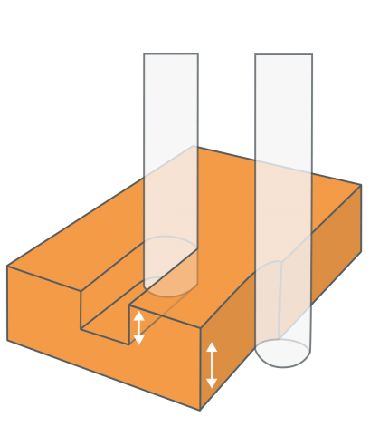
IMMERSION DEPTH
While milling a groove, we recommend the following immersion depth:
During contour milling, we recommend a lateral infeed of approx. 25 % of the end mill diameter while applying 100 % immersion depth.
The immersion depth is conditional to the milling motor, the structure and the stability of the machine. This means a reduction of the values is required, when using a less powerful and / or lighter milling motor.
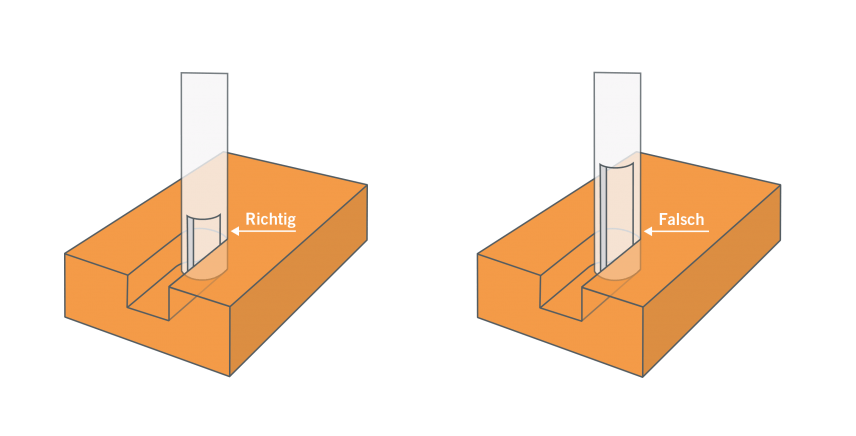
END MILL LENGTH SELECTION
To avoid increasing vibration of the end mill, we recommend clamping the bit as short as possible or as long as necessary.
COOLING / LUBRICATING
The cooling of non-ferrous metals occurs in best case with a lubrication system in combination with lubricant. Furthermore, the lubricating improves the surface quality and the service life of the tool. Lubricating with soap solution is suitable on acrylic glass. This improves an excellent surface.
DOWNCUT MILLING
In downcut milling, the end mill pulls itself into the workpiece, which can lead to the gantry or the Z-axis beeing pulled uncontrolled (backlash of lead screw) in the direction of the workpiece during the removal of larger chips. This causes a less precise milling pattern and can even result in the breakage of the end mill, if the chip building is too large.
Assuming backlash-free ball screws are used, the downcut is preferred over the upcut milling.
UPCUT MILLING
During upcut milling, the end mill pushes away from the workpiece, which, when only removing little chips, quickly causes the cutting edge to push out of the workpiece. This leads to chatter marks which create an unclean surface and reduce the endurance of the end mill.
The upcut milling is favored on machines with threaded lead screws which contain backlash.
RELIEF-GRINDED END MILLS
The maximum possible infeed is usually reduced to the spiral length of the end mill, otherwise the shank will rub on the workpiece. Due to the relief-grinded shank, depths over several infeeds up to the maximum effective lengths are possible, thus, exceeding the spiral length.
LUBRICATION SYSTEM 20-50 ML/H
increasing lube
Dependence of lubrication system on production process