Lieber Nutzer, die Forumssoftware wurde aktualisiert. Für die Erstanmeldung musst Du bitte dein Passwort zurücksetzen.
Dear user, the forum software has been updated. For the first login please reset your password.
Dear user, the forum software has been updated. For the first login please reset your password.
Benachrichtigungen
Alles löschen
Assembly and Maintenance
14
Beiträge
3
Benutzer
0
Likes
5,524
Ansichten
Themenstarter
I am currently about half way through the kit build and would like to ask couple of questions just in case.
1. There are two brass items in the parts bag that look like spacers or washers, but these are not mentioned in the manual. Are those needed anywhere?
Dimensions (difficult to measure as the parts are very thin):
Outer diameter: 8mm
Wall thickness: about 0.1mm
Length: 1mm
2. If I try to get the play or backlash out there is a situation where there is virtually no backlash in the moving part, but when I try to move the sliding assembly by hand with a constant force there is a momentary resistance in the certain part of the movement. In other words the moving assembly rolls very well at first but then slightly resists to movement for a brief moment and then continues to move smoothly again. This is both in the X and Z axis. Haven`t assembled the Y axis system yet. If I set the sysrtem so that it runs freely with the constant force I get slight backlash in the assembly (less than a mm). What would you do?
Stepcraft 600SF (version 1) parallel port
Proxxon IBS/E
Mach3
devCad Cam Pro; devWing Cam; devFus Cam; Profili Pro 2
Veröffentlicht : 19/10/2014 10:33 pm

HI Tikka,
Its great that you're building your kit. It seems so daunting at first but highly rewardable once completed so kep up the good work!
1. Please could you take a photo of the brass washer you're speaking of? All the parts in the pack have their place so they will be needed.
2.Check that the parts oncerned are nice and tight, it might just be when something is turning at a part of its turning circle there is some resistance. If this is not very much resistance then I wouldn't worry too much, but you need to get it right now as its a pain to fix later. Again a video would be great but I understand it can be a pain to upload one.
Hope this helps a bit!
Alex
Veröffentlicht : 19/10/2014 11:18 pm
Themenstarter
Thank you for helping heustec. I decided to buy the kit because that option seemed less likely to get damaged during shipping. Besides I am going to need to replace some spare parts sooner or later, so knowing how everything goes together should help. Although if I had the experience I have now, I would probably have bought the ready-to-go version, work the manual backwards, take the machine apart into subassemblies and get the feel of how things are supposed to move and go together.
So here is the photo of those two items I was writing about:

Stepcraft 600SF (version 1) parallel port
Proxxon IBS/E
Mach3
devCad Cam Pro; devWing Cam; devFus Cam; Profili Pro 2
Veröffentlicht : 20/10/2014 10:52 pm
You're right Tikka, those don't ring a bell to me.
I've looked through my manual and I can't see them in there either..where abouts were they in the packaging? WIth the rest of the kit?
Veröffentlicht : 20/10/2014 11:29 pm
They are bits left over from the brass manufacturing. They serve no purpose.
Backlash is movement/play in the drive system as the motor changes direction.
Your talking about the machine stiffness from the slides? So you are pulling the brass roller onto the Aluminium channel. You need to it to be so that the movement is "just" gone. but the slides still move. you should be able to get the slides to move freely with no play. Ignore the 1kg bit - just feel it - just enough to tighten. you can tighten them more at the end.
you want good clean easy movement with good overall machine stiffness.
Veröffentlicht : 21/10/2014 1:17 am
Ah well there you go! haha never would have guessed that!
Veröffentlicht : 21/10/2014 1:51 am
Themenstarter
They are bits left over from the brass manufacturing. They serve no purpose.
Backlash is movement/play in the drive system as the motor changes direction.
Your talking about the machine stiffness from the slides? So you are pulling the brass roller onto the Aluminium channel. You need to it to be so that the movement is "just" gone. but the slides still move. you should be able to get the slides to move freely with no play. Ignore the 1kg bit - just feel it - just enough to tighten. you can tighten them more at the end.
you want good clean easy movement with good overall machine stiffness.
I`m glad I got the brass pieces out of the way.
Yes I am talking about the machine stiffness from the slides. The problem so far was the situation when just before the play was gone, jerky movement stepped in. I applied a lot of grease to the guide surfaces this time and I think I got it now. When turning the threaded shaft with my fingers it needs some effort to move the rolling assembly. If the motors can move it without losing steps it`s all good, I hope.
Question nr 3:
I see from the manual that the longitudinal axis is Y and lateral is X. I would like to put it together so that the longitudinal is X and lateral is Y similar to the large mills I work with. I also notice that the Y axis motor is bigger than the others. Can I connect the present Y motor to the control board X terminal and vice versa or is the bigger Y motor going to fry the X circuit? Or do I connect the servos as per wiring diagram and make the change somewhere in the software settings?
Stepcraft 600SF (version 1) parallel port
Proxxon IBS/E
Mach3
devCad Cam Pro; devWing Cam; devFus Cam; Profili Pro 2
Veröffentlicht : 21/10/2014 11:45 pm
This is beyond me to be honest. Rorys the best man for that.
I would say though that its not a good idea and you should stick to how it is! The Y motor drives alot more than the X motor so probably best to leave them alone. In the software I use you cannot change the X+Y.
Veröffentlicht : 22/10/2014 11:21 am
Themenstarter
So after many assemblies and dissassemblies I finally got my 600SF together. The good news is that it looks good, the axes move and it didn`t explode or self combust after power on. 🙂
The bad news... well there are no bad news at this point because I have not made any tests to check for accuracy and missing steps.
I think I found out what I have to do about the question nr 3. Subparagraph 2.1 in the operating instructions states that no modifications are allowed unless authorized by the manufacturer in each individual case. I leave it as it is for now, but I would definitely like to change the x and y axes as the default configuration is really messing with my brain.
Stepcraft 600SF (version 1) parallel port
Proxxon IBS/E
Mach3
devCad Cam Pro; devWing Cam; devFus Cam; Profili Pro 2
Veröffentlicht : 26/10/2014 12:20 am
Jerky movement on Y axis? Make sure the two portal towers are the same distance from the back of machine - and the pulleys are working together and are both solid.
Are you using Mach3?
>>config
>>pots and pins
>>output signals
>>just swap the X and Y pin states.
you will need to check for direction and direction during homing
>>config >>homing limits "reversed etc..."
Best keeps drives wired correctly and change using SW.
No idea how to change with WinPC - someone can help here?
Veröffentlicht : 27/10/2014 5:13 am
Themenstarter
Jerky movement on Y axis? Make sure the two portal towers are the same distance from the back of machine - and the pulleys are working together and are both solid.
Are you using Mach3?
...
Yes I am using Mach3. Thank you for the reply, swapping X and Y direction/step pins did the trick. Now the portal moves where my keyboard arrows point. The homing function also seems to work. All my coordinates read zero in the end of the process.
The jerky movement was on the Z and X when I first tried to get the play out of the Z and X assembly. The problem was gone when I applied grease to the guiding rails before tensioning the black screw. When I assembled the portal onto the Y guide rails I applied grease right away so had no problem with this assembly. I measured the distance from the end plate to the portals with a calliper before and after the assembly. The difference between the portals was about 0,03mm. My measuring error is probably larger than this value so the actual difference could be more.
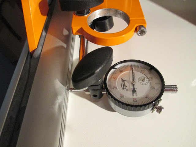
I also put a plastic triangular ruler flat onto the table with one edge aligned along the guide rail. Attached a spindle with a conical pointy tool, moved the pointy tool tip close to one edge and then moved the spindle to the other edge of the X axis. There seemed to be a slight angle in the movement (definitely a lot less than 1mm). This could also mean that the plastic triangle isn`t exactly at a 90deg angle. I purchased a dial indicator for backlash measurement and I could also slide it along the X axis (actually Y axis now since I swapped the pins :)) to see how the pointer moves. The problem is that I don`t have any calibrated metal blocks to slide it on.
Stepcraft 600SF (version 1) parallel port
Proxxon IBS/E
Mach3
devCad Cam Pro; devWing Cam; devFus Cam; Profili Pro 2
Veröffentlicht : 27/10/2014 8:24 pm
Good work!
Veröffentlicht : 27/10/2014 11:45 pm
Themenstarter
... I measured the distance from the end plate to the portals with a calliper before and after the assembly. The difference between the portals was about 0,03mm. My measuring error is probably larger than this value so the actual difference could be more.
... I purchased a dial indicator for backlash measurement and I could also slide it along the X axis (actually Y axis now since I swapped the pins) to see how the pointer moves. The problem is that I don`t have any calibrated metal blocks to slide it on.
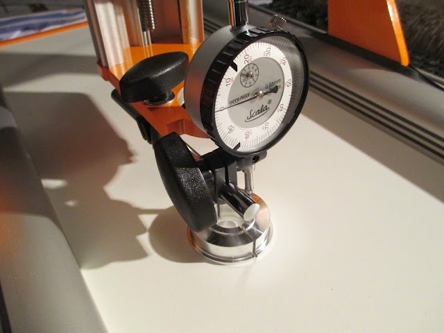
I played around with the dial indicator today and it looks like I was a bit hasty with the calliper before and saw what I wanted to see. I placed a spirit level on top of the guide rails against the orange end plate and slid along the surface with the indicator tip. The pointer moved about 0,55mm. Then turned the level around and checked on the other side. Also used an aluminum U-profile for the same test. The results were about the same. To make corrections I loosened the belt cover, pulled the machine plate enough to make a gap, loosened the belt tensioning bearings, took the belt off from one side, moved one portal side to catch up and then put the parts back together again. The best result I could achieve was 0,1mm along the distance of 180mm.
The dial indicator came with a magnetic fixture so I used parts of that to fix the indicator to the machine. The screw was a lot narrower than the dust extractor fixing hole but washers on either side seemed to hold it sturdily enough. Measured and corrected 0,01mm backlash for X and Y. The Z seemed to have no backlash. I took ISO 2768-1 m tolerances as my target to achieve, looks promising at the moment. Anxious to see how the machine actually performs.


Stepcraft 600SF (version 1) parallel port
Proxxon IBS/E
Mach3
devCad Cam Pro; devWing Cam; devFus Cam; Profili Pro 2
Veröffentlicht : 28/10/2014 9:04 pm
looks very comprehensive and interesting test.
let us know how you get on.
lets see some chips flying.
Veröffentlicht : 28/10/2014 9:14 pm
